


Structure and principle of foam cutting equipment
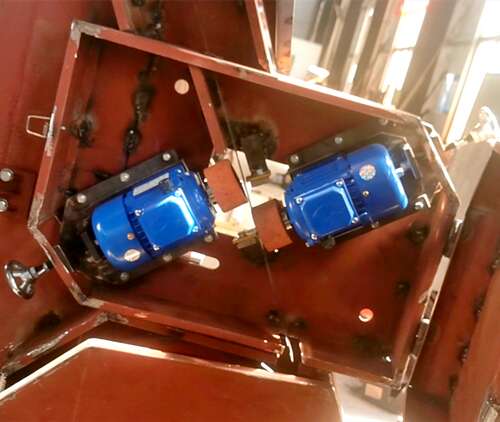
Foam horizontal cutting machine found the cause of failure, analysis of equipment structure principle
1, the reason why
The connection between the servo motor shaft and the lead screw is loose, which causes the lead screw and the motor to be out of sync, resulting in size error.
Analysis of the
When detecting, just make a mark on the coupling of the servo motor and the lead screw, and move the table (or tool rest) back and forth with a faster rate. Because of the inertia of the table (or turret), both ends of the coupling will appear obvious relative movement. This kind of fault is usually shown as the processing size changes only in one direction, only the coupling screw uniform fastening can be eliminated.
2、why
Poor lubrication between the ball screw and the nut, so that the movement resistance of the table (or tool rest) increases, and the movement instruction can not be fully executed accurately.
Analysis of the
Such faults are usually shown as irregular changes in the size of parts within the range of a few wires, which can be eliminated by improving lubrication.
3、why
Machine tool table (or tool rest) movement resistance is too large, generally for the insert adjusting too tight, machine tool guide rail surface lubrication is poor.
Analysis of the
The fault phenomenon is generally manifested as irregular changes in the size of parts within the range of a few threads. The inspection can be carried out by observing the size and change of dGN800-804's position deviation, which is usually large when it is stationary in the positive and negative directions. This kind of failure only needs to readjust the insert and improve the lubrication of the guide rail.
4、why
Rolling bearing wear or improper adjustment, resulting in excessive movement resistance.
Analysis of the
The fault phenomenon is also usually characterized by irregular changes in size within a few threads. The check can be carried out by the position deviation of DGN800-804, the method is the same as above. This kind of fault only needs to replace the worn bearing and carefully adjust, the fault can be eliminated.
5、why
Improper clearance or clearance compensation amount of lead screw.
Analysis of the
The fault can be eliminated by adjusting the clearance or changing the clearance compensation value.
Processing size unstable fault judgment and maintenance
Polyurethane foam cutting machine, failure causes and solutions
(1) The workpiece size is accurate and the surface finish is poor
The cause of the problem
1. The tool tip is damaged and not sharp
2. The machine tool has resonance and is not placed smoothly
3. The machine crawls
4. Poor processing technology
Solution (compare with above)
1. Tool wear or damage is not sharp, then re-sharpen the knife or choose a better tool to re-tool
2. Machine tool resonance or placement is not stable, adjust the level, lay the foundation, fixed and stable
3. The reason for mechanical crawling is that the guide rail of the drag plate is badly worn, and the ball screw is worn or loose. Machine tools should pay attention to maintenance, should clean the wire after work, and add lubricating oil in time to reduce friction
4. Select coolant suitable for workpiece processing; In order to meet the requirements of other processes, choose a higher spindle speed as far as possible
(2) workpiece taper size head phenomenon
The cause of the problem
1. The machine tool placement level is not adjusted well, one is high and one is low, resulting in unstable placement
2. When turning the long shaft, the workpiece material is hard and the tool is deep, resulting in the phenomenon of letting the knife
3. Tailstock thimble is different from spindle
The solution
1. Use a level to adjust the levelness of the machine tool, lay a solid foundation, and fix the machine tool to improve its toughness
2. Choose reasonable technology and appropriate cutting feed to avoid cutting tool force
3. Adjust tailstock
(3) The driver phase lamp is normal, and the size of the workpiece is large or small
The cause of the problem
1. The machine tool pallet runs at a high speed for a long time, leading to screw and bearing wear
2. The repeated positioning accuracy of tool rest produces deviation in long-term use
3. The drag plate can accurately return to the starting point of processing each time, but the size of the workpiece is still changing. This phenomenon is generally caused by the spindle, the high-speed rotation of the spindle makes the bearing wear seriously, resulting in the change of processing size
Solution (compare with above)
1. Use dial indicator to lean on the bottom of tool rest, edit a fixed cycle program through the system at the same time, check the repeated positioning accuracy of the drag plate, adjust screw clearance, and replace the bearing
2. Check the repeated positioning accuracy of tool rest with dial indicator, adjust the machine or replace the tool rest
3. Use dial indicator to test whether the workpiece can be returned to the starting point of the program accurately; If possible, overhaul the spindle and replace the bearing
(4) the size of the workpiece differs from the actual size by a few millimeters, or there is a great change in an axial direction
The cause of the problem
1. The speed of fast positioning is too fast, and the drive and motor can not react
2. After long-term friction and wear, the mechanical drag plate screw and bearing are too tight and jammed
3. The lock is not tight because the tool holder is too loose after the tool change
4. Editing program error, end without echo or cancel knife filling
5. The electronic gear ratio or step Angle of the system is incorrectly set
Solution (compare with above)
1. If the fast positioning speed is too fast, the speed, cutting speed and time of G0 should be properly adjusted to make the driver and motor operate normally at the rated operating frequency
2. After the machine tool wear, the drag plate, screw and bearing are too tight and stuck, so it must be readjust and repaired
3. If the tool rest is too loose after tool change, check whether the tool rest reversal time is satisfied, check whether the turbine vortex rod inside the tool rest is worn, whether the clearance is too large, whether the installation is too loose, etc
4. If it is caused by the program, it must modify the program, improve in accordance with the requirements of the workpiece drawings, choose a reasonable processing technology, and write the correct program in accordance with the instructions of the manual
5. If the size deviation is too large, check whether the system parameters are set properly, especially whether the parameters such as electronic gear ratio and step Angle are damaged. This phenomenon can be measured by typing hundreds of tables
(5) The effect of arc processing is not ideal, the size is not in place
The cause of the problem
1. The overlap of vibration frequencies leads to resonance
2. Processing technology
3. Unreasonable parameter setting and excessive feed speed make arc machining out of step
4. Loose screw clearance caused by large or screw too tight caused by out of step
5. The timing belt is worn
The solution
1. Find out the resonant parts and change their frequency to avoid resonance
2. Consider the processing technology of workpiece materials and make reasonable programs
3. For stepper motors, the processing rate F cannot be set too high
4. Whether the machine is firmly installed, placed smoothly, whether the drag plate is too tight after wear, clearance increases or tool rest loosens, etc
5. Replace the synchronization belt
(6) In batch production, workpiece out-of-tolerance occasionally occurs
The cause of the problem
1. Occasionally there is a change in the size of a piece in mass production, and then it returns to normal without modifying any parameters for reprocessing
2. Occasionally in the mass production, a piece of size is not correct, and then continue to process the size is still unqualified, but after the knife is correct again
The solution
1. Must carefully check the fixture, and take into account the operator's operation method, and the reliability of clamping; Due to the size change caused by clamping, it is necessary to improve the tooling so that workers can avoid human negligence and misjudgment as much as possible
2. Numerical control system may be affected by the fluctuation of external power supply or interference after automatic interference pulse, transmitted to the drive causing the drive to accept excess pulse drive motor more or less go phenomenon; Understand the law, try to use some anti-interference measures, such as: strong electric field interference of strong electric cable and signal line isolation of weak electric signal, adding anti-interference absorption capacitor and using shielding line isolation. In addition, check whether the ground is firmly connected, grounding contact is close, take all anti-interference measures to avoid interference system
(7) the workpiece is processed in one process, and the size of other processes is accurate
The cause of the problem
Whether the parameters of the program segment are reasonable, whether they are in the predetermined trajectory, and whether the programming format meets the requirements of the specification
The solution
Thread program segment appears disorderly teeth, the pitch is not correct, then immediately associated with the processing of thread peripheral configuration (encoder) and the objective factors of the function, such as: The relation between spindle speed, thread lead and feed speed (928 TC with DY3, spindle speed X thread lead ≤1700 mm/min when machining thread), the line number of encoder is consistent with the computer setting; When it is found that the size of the circular plate program segment is not correct, check whether the programming trajectory of the arc is on the same arc and whether there is any excessive relationship between special circles
(8) Each process of the workpiece has the phenomenon of increasing or decreasing
The cause of the problem
1. Programming errors
2. The system parameters are incorrectly set
3. The configuration is incorrect
4. Mechanical transmission parts have regular periodic changes of failure
The solution
1. Check whether the instructions used in the program are executed according to the requirements specified in the instruction manual. You can judge by making hundreds of tables
2. Check whether the system parameters are properly set or manually changed
3. Whether the calculation of coupling parameters in connection calculation of relevant machine configuration meets the requirements and whether the pulse equivalent is accurate
4. Check whether the transmission part of the machine tool is damaged, whether the gear coupling is uniform, and whether there are periodic and regular faults. If so, check the key parts and exclude them
The cause of the problem
1. The tool tip is damaged and not sharp
2. The machine tool has resonance and is not placed smoothly
3. The machine crawls
4. Poor processing technology
Solution (compare with above)
1. Tool wear or damage is not sharp, then re-sharpen the knife or choose a better tool to re-tool
2. Machine tool resonance or placement is not stable, adjust the level, lay the foundation, fixed and stable
3. The reason for mechanical crawling is that the guide rail of the drag plate is badly worn, and the ball screw is worn or loose. Machine tools should pay attention to maintenance, should clean the wire after work, and add lubricating oil in time to reduce friction
4. Select coolant suitable for workpiece processing; In order to meet the requirements of other processes, choose a higher spindle speed as far as possible
(2) workpiece taper size head phenomenon
The cause of the problem
1. The machine tool placement level is not adjusted well, one is high and one is low, resulting in unstable placement
2. When turning the long shaft, the workpiece material is hard and the tool is deep, resulting in the phenomenon of letting the knife
3. Tailstock thimble is different from spindle
The solution
1. Use a level to adjust the levelness of the machine tool, lay a solid foundation, and fix the machine tool to improve its toughness
2. Choose reasonable technology and appropriate cutting feed to avoid cutting tool force
3. Adjust tailstock
(3) The driver phase lamp is normal, and the size of the workpiece is large or small
The cause of the problem
1. The machine tool pallet runs at a high speed for a long time, leading to screw and bearing wear
2. The repeated positioning accuracy of tool rest produces deviation in long-term use
3. The drag plate can accurately return to the starting point of processing each time, but the size of the workpiece is still changing. This phenomenon is generally caused by the spindle, the high-speed rotation of the spindle makes the bearing wear seriously, resulting in the change of processing size
Solution (compare with above)
1. Use dial indicator to lean on the bottom of tool rest, edit a fixed cycle program through the system at the same time, check the repeated positioning accuracy of the drag plate, adjust screw clearance, and replace the bearing
2. Check the repeated positioning accuracy of tool rest with dial indicator, adjust the machine or replace the tool rest
3. Use dial indicator to test whether the workpiece can be returned to the starting point of the program accurately; If possible, overhaul the spindle and replace the bearing
(4) the size of the workpiece differs from the actual size by a few millimeters, or there is a great change in an axial direction
The cause of the problem
1. The speed of fast positioning is too fast, and the drive and motor can not react
2. After long-term friction and wear, the mechanical drag plate screw and bearing are too tight and jammed
3. The lock is not tight because the tool holder is too loose after the tool change
4. Editing program error, end without echo or cancel knife filling
5. The electronic gear ratio or step Angle of the system is incorrectly set
Solution (compare with above)
1. If the fast positioning speed is too fast, the speed, cutting speed and time of G0 should be properly adjusted to make the driver and motor operate normally at the rated operating frequency
2. After the machine tool wear, the drag plate, screw and bearing are too tight and stuck, so it must be readjust and repaired
3. If the tool rest is too loose after tool change, check whether the tool rest reversal time is satisfied, check whether the turbine vortex rod inside the tool rest is worn, whether the clearance is too large, whether the installation is too loose, etc
4. If it is caused by the program, it must modify the program, improve in accordance with the requirements of the workpiece drawings, choose a reasonable processing technology, and write the correct program in accordance with the instructions of the manual
5. If the size deviation is too large, check whether the system parameters are set properly, especially whether the parameters such as electronic gear ratio and step Angle are damaged. This phenomenon can be measured by typing hundreds of tables
(5) The effect of arc processing is not ideal, the size is not in place
The cause of the problem
1. The overlap of vibration frequencies leads to resonance
2. Processing technology
3. Unreasonable parameter setting and excessive feed speed make arc machining out of step
4. Loose screw clearance caused by large or screw too tight caused by out of step
5. The timing belt is worn
The solution
1. Find out the resonant parts and change their frequency to avoid resonance
2. Consider the processing technology of workpiece materials and make reasonable programs
3. For stepper motors, the processing rate F cannot be set too high
4. Whether the machine is firmly installed, placed smoothly, whether the drag plate is too tight after wear, clearance increases or tool rest loosens, etc
5. Replace the synchronization belt
(6) In batch production, workpiece out-of-tolerance occasionally occurs
The cause of the problem
1. Occasionally there is a change in the size of a piece in mass production, and then it returns to normal without modifying any parameters for reprocessing
2. Occasionally in the mass production, a piece of size is not correct, and then continue to process the size is still unqualified, but after the knife is correct again
The solution
1. Must carefully check the fixture, and take into account the operator's operation method, and the reliability of clamping; Due to the size change caused by clamping, it is necessary to improve the tooling so that workers can avoid human negligence and misjudgment as much as possible
2. Numerical control system may be affected by the fluctuation of external power supply or interference after automatic interference pulse, transmitted to the drive causing the drive to accept excess pulse drive motor more or less go phenomenon; Understand the law, try to use some anti-interference measures, such as: strong electric field interference of strong electric cable and signal line isolation of weak electric signal, adding anti-interference absorption capacitor and using shielding line isolation. In addition, check whether the ground is firmly connected, grounding contact is close, take all anti-interference measures to avoid interference system
(7) the workpiece is processed in one process, and the size of other processes is accurate
The cause of the problem
Whether the parameters of the program segment are reasonable, whether they are in the predetermined trajectory, and whether the programming format meets the requirements of the specification
The solution
Thread program segment appears disorderly teeth, the pitch is not correct, then immediately associated with the processing of thread peripheral configuration (encoder) and the objective factors of the function, such as: The relation between spindle speed, thread lead and feed speed (928 TC with DY3, spindle speed X thread lead ≤1700 mm/min when machining thread), the line number of encoder is consistent with the computer setting; When it is found that the size of the circular plate program segment is not correct, check whether the programming trajectory of the arc is on the same arc and whether there is any excessive relationship between special circles
(8) Each process of the workpiece has the phenomenon of increasing or decreasing
The cause of the problem
1. Programming errors
2. The system parameters are incorrectly set
3. The configuration is incorrect
4. Mechanical transmission parts have regular periodic changes of failure
The solution
1. Check whether the instructions used in the program are executed according to the requirements specified in the instruction manual. You can judge by making hundreds of tables
2. Check whether the system parameters are properly set or manually changed
3. Whether the calculation of coupling parameters in connection calculation of relevant machine configuration meets the requirements and whether the pulse equivalent is accurate
4. Check whether the transmission part of the machine tool is damaged, whether the gear coupling is uniform, and whether there are periodic and regular faults. If so, check the key parts and exclude them
Latest News
Contact Us

Name: Dylane shi
E-mail: [email protected]
QQ: 627812212
WeChat: qd627812212
Whatsapp: +8618061811323
Add: Qingdao City, Shandong


Link

 WhatsApp
  Mail inquiry
 QQ online