CHINESE
 ENGLISH


Structure principle of polyurethane foam disc cutting machine
Abstract:
This paper introduces the modification scheme of PU foam flat cutting machine control system and the speed control device of disc speed regulating motor by using PLC control system and frequency conversion speed regulating system. The modified system has the advantages of easy operation, good stability and energy saving.
Key words: PLC control; Frequency control; Sponge disc flat cutting machine, foam cutting machine
1、An overview of the
With the development of modern production equipment control technology and the emphasis on energy saving and emission reduction, the stability and energy saving effect of foam production equipment become an important issue in equipment operation. In the processing and production of polyurethane foam products, foam contour crosscutting machine is a common equipment. Because the electrical control system of the equipment is controlled by relay, and the operation panel is controlled by buttons and switches, the control circuit is complicated, the contact points are many, and the failure rate is high. In addition, the driving motor of the platform is driven by electromagnetic speed regulating motor, which often appears out of control and low efficiency. In the production often because of the above problems lead to shutdown maintenance, in view of these situations, put forward using PLC control and frequency conversion speed control scheme to the equipment's electrical control system and disk drive motor drive for transformation, effectively improve the equipment performance, improve the production efficiency.2、The usage and main structure of sponge PU foam flat cutting machine are introduced
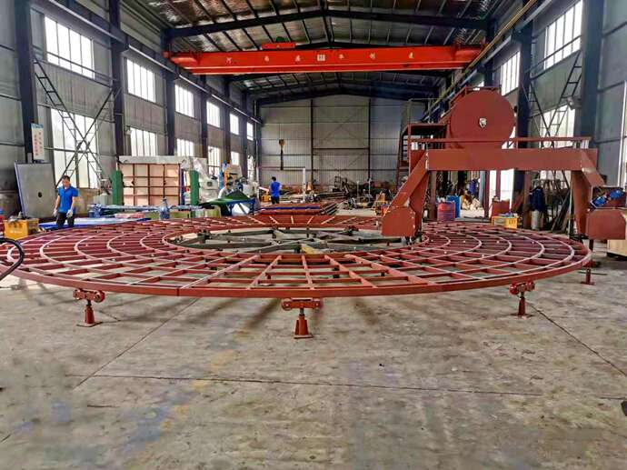
Sponge foam flat cutting machine is used to continuously cut large foam parts into 2-150mm sheet PU foam. Foam disc flat cutting machine is mainly composed of disk table, machine base, tool rest, control device. The foam disc worktable is composed of speed regulating motor, worm gear reducer, brake, friction wheel disc platform, roller and base. The disk platform is a rotary table with a diameter of 7m. The original driving motor uses a 2.2kW electromagnetic speed regulating motor, with a speed regulating range of 125-1250r/min. After the reduction drive, the disk speed range is 0.347-3.47r/min. The machine base is composed of brake motor, worm gear reducer, drive shaft, bevel gear, base and column, etc. After the brake motor decelerates, it controls the tool rest to rise or fall at the speed of 2.37mm/min. The tool holder is composed of a tool belt motor, a tool wheel, a tool belt, a tool grinding motor and a tool grinding device.3、Main circuit setting
According to the main structure and working needs of foam disc flat cutting machine, the main circuit is modified, and the circuit structure after modification is shown in Figure 1. In the figure, Q1-Q3 air switch is added to protect each part of the fault; Increased the upper limit and lower limit of tool rest photoelectric detection; Use frequency conversion speed control motor device instead of the original electromagnetic speed control motor; MD204L text display instead of all the original indicators and total counter, lifting distance display and thickness setting input device.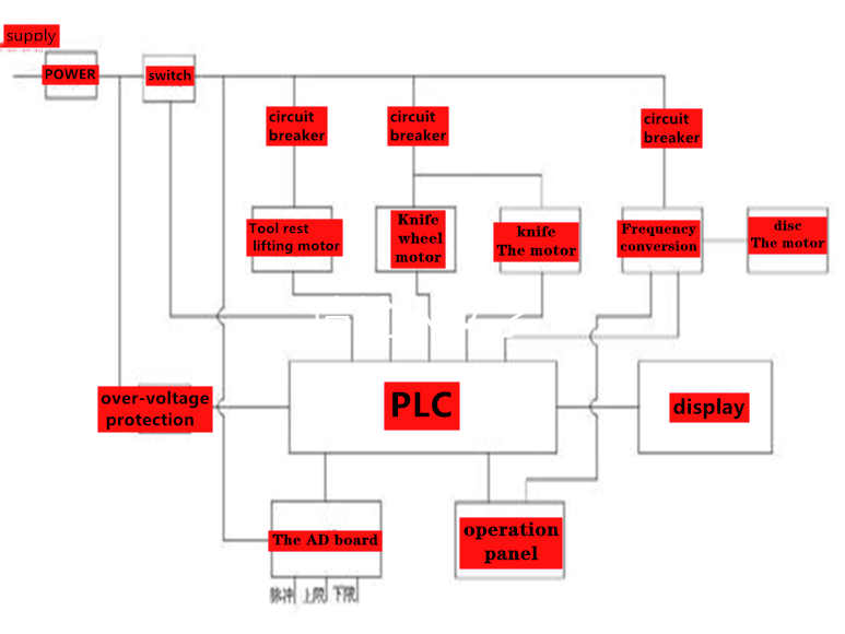
4, sponge foam disc flat cutting machine PLC control frequency conversion speed control compared with the original electromagnetic speed control, with smooth start operation, simple operation, disk drive
4.1 Manual operation of the control motor heat less. Effectively solve the original disc low speed trembling, relay caused by more.
The equipment adopts digital disk photoelectric sensor to detect the lifting distance of tool rest. The detection signal has been adopted by enterprises and played a role in production due to the problems of release delay and high failure rate.
AD circuit board conversion input, in order to ensure accurate counting, the use of C235 high-speed counter. The tool rest has been running for more than a year and has been affirmed by the users.
Down to increase count, tool rest up to decrease count. The disc is reset once a week, and the counter shows a value of 0.1mm; The total power switch is QF leakage switch, and the rest power is controlled by AC contactor. SB1 is the start and stop button, designed for alternate control mode; SB2 is the tool rest rising control button. If SB2 is operated for less than 1.5 seconds, it is the point rising, and if SB2 is operated for more than 1.5 seconds, it is the self-locking rising.
SB3 is the tool rest drop control button. If SB3 is operated for less than 1.5 seconds, it will be the point drop, and if SB3 is operated for more than 1.5 seconds, it will be the self-lock drop. SB4 is the total tool rest stop control button (in order to prevent the motor from instantaneous positive and negative control, press SB3 to stop KM2 in continuous rise, press SB2 to stop KM3 in continuous decline, and only press SB2 and SB3 to switch on the output when the motor stops); SB5 is the knife belt operation control button,
SB6 is the grinding motor control button, SB7 is the disc forward control button, SB10 is the disc back control button, the above control buttons use alternate control mode to control the corresponding motor, disk drive motor adopts inverter control
4.2 Control of automatic operation
SB9 is an alternate button for automatic or manual operation, S1 and S2 are dry spring tubes for detecting disk position,D200 is the input of predetermined slice thickness, and the numerical step is 0.1mm. The operation state is manual control when starting up. When pressing SB9 button, automatic operation starts, and the motor with the blade is running. After 2 seconds, the disk motor is automatically turned forward through the frequency conversion governor. When a disc magnet triggers the reed S1 after cutting, the disc motor stops and the tool rest motor falls. After the photoelectric sensor detects the motor revolution and converts it to AD circuit board, the input starts counting. When C235 is equal to or greater than the predetermined thickness of D200, the tool rest stops falling and the disk motor continues to move forward. When the reed tube S2 is disconnected, C235 resets and enters the next cut.
4.3 Tool rest and emergency stop protection
SB10 is the emergency stop button, which stops all output signals in case of emergency; Photoelectric detection sensor is used to protect the lower limit and upper limit of tool rest
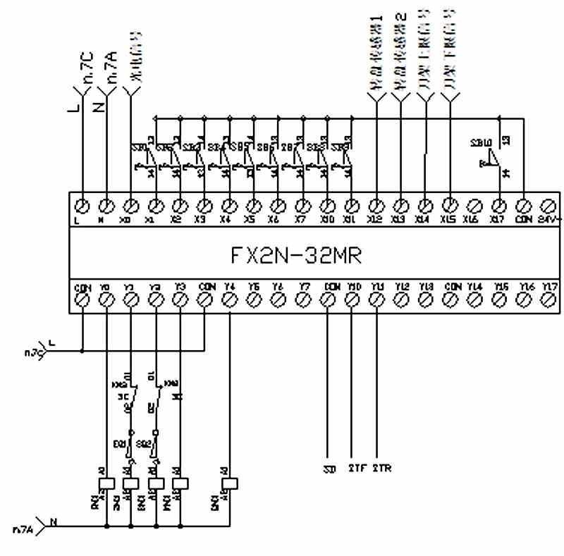
5. PLC, inverter selection, program and input/output distribution diagram
According to the input and output points of sponge disc flat cutting machine, Mitsubishi FX2N-32MR programmable controller is selected. According to the disk drive motor frequency conversion speed control requirements, Mitsubishi FR-D740 compact multi-function inverter is selected, power range 0.4-7.5KW. It can meet the control requirements of transforming the original equipment with PLC and inverter control (speed adjustment using external control working mode, through the potentiometer manual control of speed, positive and negative by PLC output control). The I/O allocation diagram is shown in figure 2.
6 the conclusion
Compared with the original relay control device, the improved PLC control system has increased the function of text display monitoring and bidirectional counting. Reduced the number of connections, relays and operation buttons; The circuit structure diagram modified in Figure 1 has the characteristics of strong reliability, good safety performance, accurate limit and display, and safe and simple control panel.
Latest News
Contact Us

Name: Dylane shi/ Henry
E-mail: [email protected]
QQ: 627812212
WeChat: qd627812212
Whatsapp: +8618061811323
Whatsapp: +8613210076180
Add: Qingdao City, Shandong


Link

 WhatsApp
  Mail inquiry
 QQ online